5G-Service Based Interface Application
The 5G-Service Based Interface (5G-SBI) application synthesizes HTTP2 transactions with proper L2, L3, and L4 headers from JSON-encoded data received from Ericsson vTAPs via UDP-GRE. The 5G-SBI application takes the raw encoded data that monitoring tools cannot understand and reconstructs complete, tool-facing packets with valid TCP flows.
The 5G-SBI application operates on a DPDK-based V Series Node and supports the following traffic types:
-
SBI traffic (L7-JSON) - AMF, SMF signaling from Ericsson PCC vTAPs (key value 1). The 5G-SBI application synthesizes this traffic into HTTP2 packets.
-
Non-SBI traffic - PSVP, GTPC, Diameter, and other protocols from Ericsson PCC vTAPs (key values 5, 7, 9, 11, 15, 21, 23). The PCAPng application reads the data from the Enhanced Packet Block and forwards it directly to the egress tunnel without synthesis.
Ericsson vTAP
Ericsson virtual TAPs (vTAPs) mirror traffic from 5G Core network functions. Each network function module has its own vTAP. Ericsson PCC (Packet Core Controller) contains vTAPs for AMF, SMF, and other protocols. Ericsson CCx (Cloud Core) contains vTAPs for SCP traffic.
Each vTAP assigns a key value to identify the protocol type. The vTAP wraps the mirrored packet in PCAPng format (Enhanced Packet Block) and sends it over a UDP-GRE tunnel to the GigaVUE V Series Node.
The following table lists the Ericsson vTAP key values and their corresponding traffic types:
|
Key Value |
Traffic Type |
Category |
|
0,2 |
Metadata (domain classification) |
Control |
|
1 |
AMF, SMF |
SBI (L7-JSON) |
|
3, 17, 19 |
SCP protocols |
SBI (L7-Native) |
|
5, 7, 9, 11, 15, 21, 23 |
PSVP, GTPC, Diameter |
Non-SBI |
Note: Key values 0 and 2 carry domain metadata only. This traffic is processed by the PCAPng application in Primary mode to identify which flow belongs to which domain. This traffic does not go to monitoring probes.
Ericsson vTAP Domain Tagging
Ericsson vTAP components mirror control plane and selected user plane traffic, for example, from Ericsson PCC nodes, and send it to the GigaVUE V Series using UDP‑GRE with PCAPng/JSON metadata. Previously, the 5G‑SBI application treated all mirrored flows uniformly, requiring monitoring tools to independently infer the Ericsson domain (for example, pc‑mm, pc‑sm, sc‑scp) and the associated 3GPP interface.
With Domain Tagging, the PCAPng application on V Series reads the Ericsson vTAP metadata, identifies the Ericsson domain for each flow, and assigns a VLAN ID based on a configurable domain to VLAN map. When you enable domain classification in the PCAPNG app and VLAN tagging on the VXLAN or L2GRE egress tunnel, V Series tags each packet with the appropriate VLAN so probes can separate domains simply by filtering on VLAN.
You can also reserve VLANs for:
| Traffic mapped to the others domain (for example, unsupported or unexpected Ericsson domains) |
| Traffic mapped to the unclassified domain (for example, traffic for which domain information is not yet available) |
Encoded messages from the Ericsson vTAP contain Kubernetes Pod ephemeral IP addresses for NF instances, which are internal to the Ericsson deployment and not accessible outside the Kubernetes cluster. Because these IPs cannot be used externally, the 5G SBI application always maps the NF identifiers (NF instance ID and FQDN) in the encoded message to the configured ingress IP address using the string‑to‑IP mapping table.
The NF instance ID and FQDN ID must be provided in the form of CSV file. You can upload the CSV file through GigaVUE‑FM.
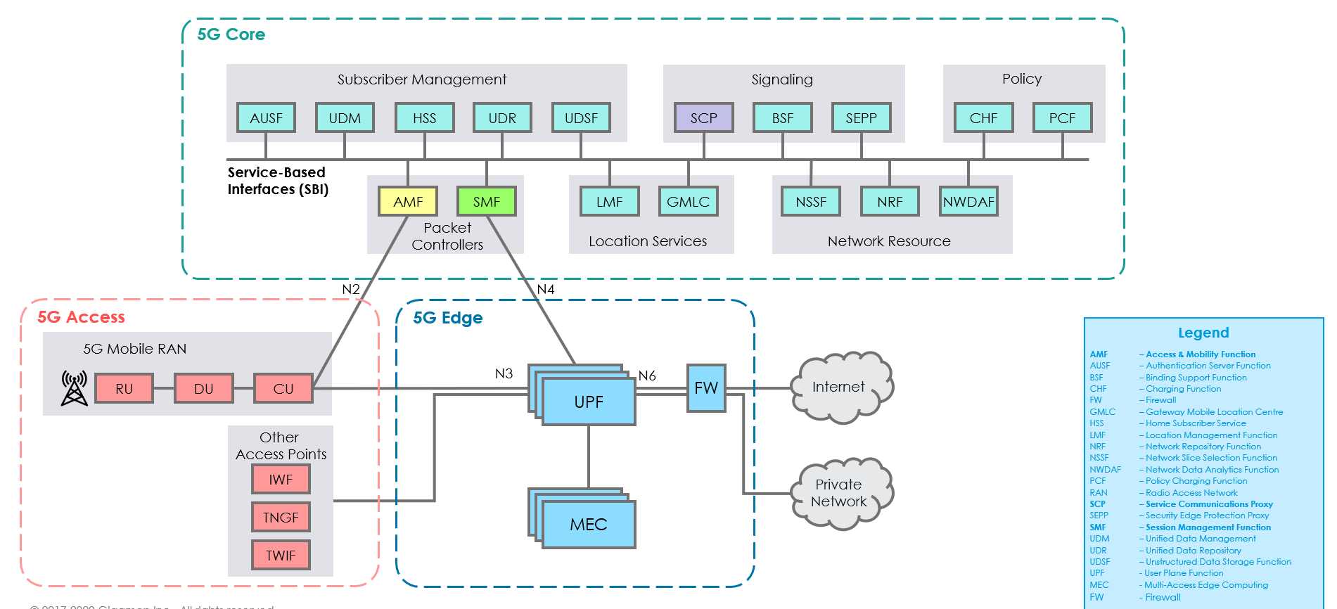
How SBI Application works
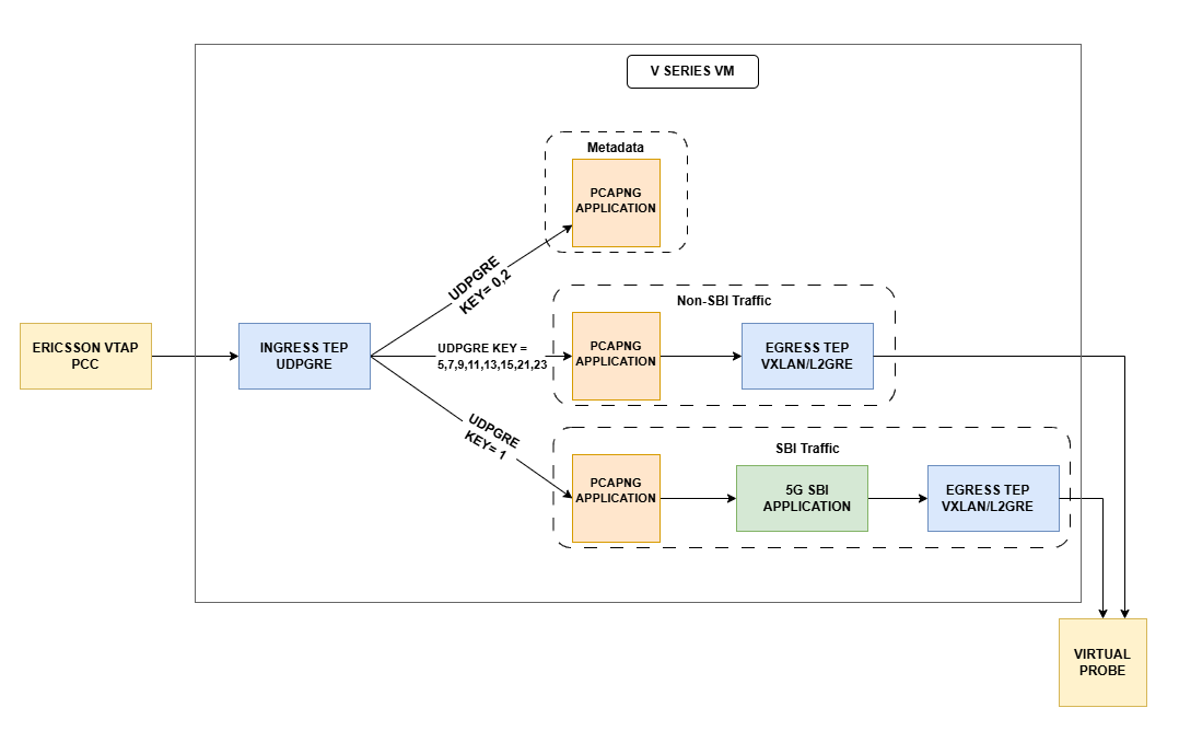
In the GigaVUE V Series Node, the SBI application receives the HTTP2 transaction messages as JSON encoded data from the PCAPng application, which in turn receives the data from the UDP‑GRE TEP.
The SBI application:
| 1. | Parses the JSON data to extract source and destination information, ports, and message type (request/response). |
| 2. | Synthesizes a complete HTTP/2 transaction with L2, L3, and L4 headers, along with the HTTP/2 headers and body from the original transactions. |
| 3. | Sends the synthesized packets to the egress TEP, which forwards them to the appropriate virtual probes. |
The following image shows the block diagram of the data flow in the V Series Node containing the SBI application.
Supported Platforms:
The application is supported on the following platforms:
| VMware ESXi |
| OpenStack |
| Third Party Orchestration |
Rules and Notes
| The maximum number of HTTP2 headers (in the synthesized HTTP2 transactions) that is supported is 64. |
| The PCAPng application that is linked to 5G-SBI application (on the right side) should only be linked to UDP-GRE TEP with key value 1 on the left side. If it is linked to other UDP-GRE TEPs (key values other than 1), then the behavior cannot be defined and leads to unexpected results. |
| The maximum number of NF and FQDN entries supported is 4K. |
| In 5G-SBI application, the V Series node can log the following details to CSV files: |
| Transaction details - Represents the transaction or flow of request and response packets into the application. The details of the flow or transaction are recorded in the CSV file for 5 minutes or 60 minutes based on the configuration. |
| Flow statistics details - Represents the packet and flow statistics in 60 seconds time interval. |
These files help you to understand the records and traffic efficiently. The files are named as per the date and time in which the files were created. When the number and size of files grow, the application automatically detects the old files and deletes them.
| Ericsson vTAP domain tagging can be configured only in primary mode when configuring Pcapng application. Refer to 5G-Service Based Interface Application. |
5G-Ericsson vTAP Packet Processing (5G-EVP)
The 5G-Ericsson vTAP Packet Processing (5G-EVP) application orders packets received from Ericsson vTAP sources and optionally decrypts DTLS(Datagram Transport Layer Security)-encrypted traffic before forwarding it to the downstream 5G-SBI and 5G-Cloud applications.
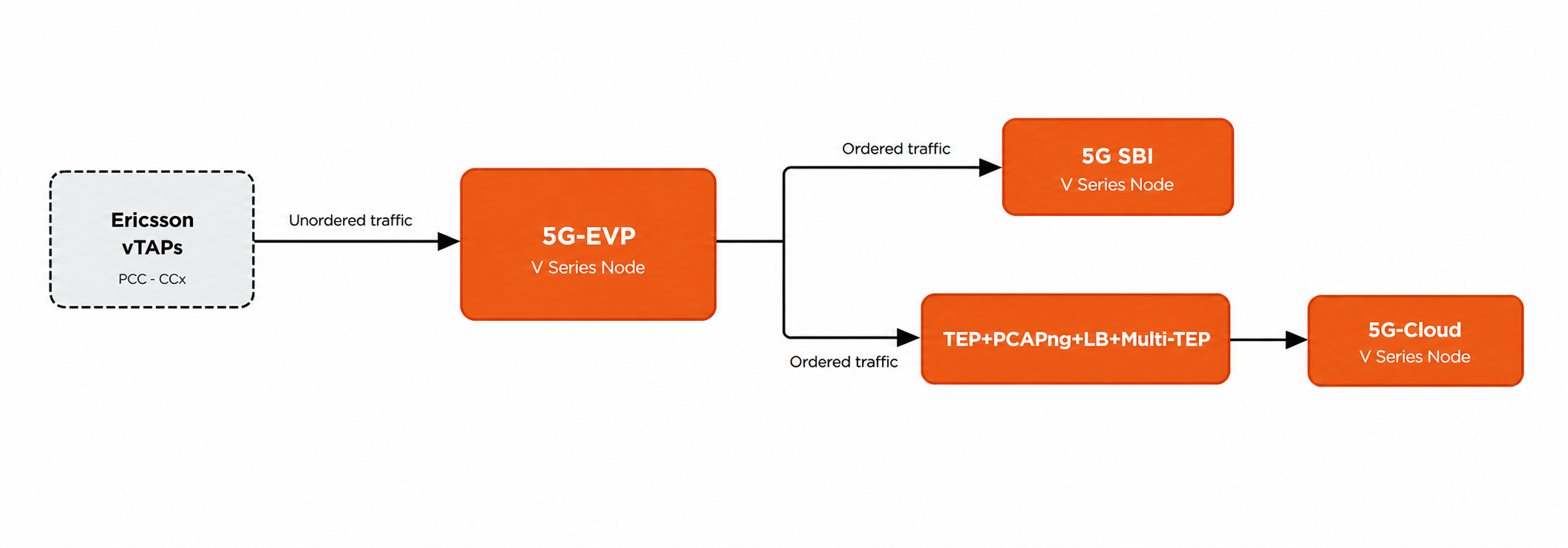
When multiple Ericsson vTAPs send traffic simultaneously, packets can arrive at the V Series Node out of order. Out-of-order packets can prevent monitoring probes from building session tables correctly, resulting in lost traffic visibility. The 5G-EVP application addresses this by ordering packets based on the timestamp at which each packet was originally observed on the network, ensuring that downstream applications and monitoring probes receive traffic in the correct sequence.
The 5G-EVP application runs on a dedicated V Series Node and sits in front of the existing 5G-SBI and 5G-Cloud nodes. It does not modify or replace those applications.
Note: The 5G-SBI and 5G-Cloud applications can operate without the 5G-EVP application. If packet ordering is not required, use the existing two-node deployment. However, the 5G-EVP application requires a downstream 5G-SBI or 5G-Cloud application to function.
Solution Architecture
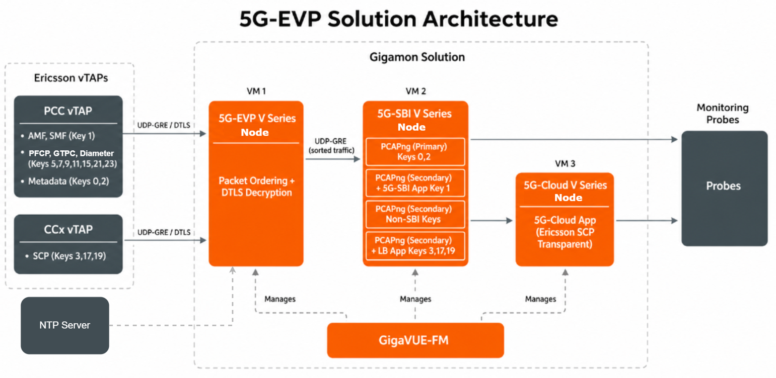
The complete Ericsson vTAP solution with the 5G-EVP application uses three V Series Nodes managed by GigaVUE‑FM. Each V Series Node requires a separate Monitoring Domain and a separate Monitoring Session.
|
V Series Apps |
GigaVUE-FM |
|
5G-EVP V Series Node |
Orders packets from Ericsson vTAPs based on embedded timestamps and forwards ordered traffic to the downstream V Series Nodes over UDP-GRE. Optionally decrypts DTLS-encrypted traffic. |
|
5G-SBI V Series Node
|
SBI and Non-SBI pipeline: Processes SBI (L7-JSON) traffic through the 5G-SBI application for synthesis. Forwards non-SBI traffic directly to egress tunnels. |
|
SCP pipeline: Distributes SCP (L7-Native) traffic through the LB application to multi-tap egress tunnels for downstream processing by the 5G-Cloud Node. |
|
|
5G-Cloud V Series Node |
Processes SBI (L7-Native) traffic from Ericsson SCP using the 5G-Cloud application. |
|
GigaVUE-FM |
Configures and monitors all three V Series Nodes. Manages NTP server configuration for the 5G-EVP Node. |
Recommended VM Specifications
|
V Series Node |
vCPUs |
Memory |
Disk Space |
|
5G-EVP |
20 |
32 GB |
80 GB |
|
5G-SBI |
8 |
16 GB |
80 GB |
|
5G-Cloud |
24 |
32 GB |
80 GB |
Recommended VM Specifications (DTLS)
|
V Series Node |
vCPUs |
Memory |
Disk Space |
|
5G-EVP |
32 |
32 GB |
80 GB |
|
5G-SBI |
8 |
16 GB |
80 GB |
|
5G-Cloud |
24 |
32 GB |
80 GB |
Supported Deployment Combinations
The following table lists the supported deployment combinations. SBI and non-SBI traffic always coexist on the same 5G-SBI monitoring session. SCP traffic can be deployed independently or alongside SBI/non-SBI traffic.
|
Combination |
Monitoring Sessions Required |
|
SBI + Non-SBI traffic |
EVP + 5G-SBI |
|
SCP traffic |
EVP + LB App + Multi-TEP VM + 5G-Cloud |
|
SBI + Non-SBI + SCP |
EVP + 5G-SBI + 5G-Cloud |
Supported Platforms
-
VMware ESXi (FM orchestration and third-party orchestration)
-
OpenStack (FM orchestration and third-party orchestration)
Licensing
No new license is required. The 5G-EVP application is included in the existing V Series 5GC add-on license.
Overview of Packet Ordering
When multiple Ericsson vTAPs send traffic simultaneously, packets can arrive at the V Series Node out of order. Out-of-order packets can prevent monitoring probes from building session tables correctly, resulting in lost traffic visibility.
The 5G-EVP application orders packets based on the timestamp at which each packet was originally observed on the network. The application maintains a configurable time window and uses this window to hold incoming packets, order them by observed timestamp, and forward them in the correct sequence to the downstream 5G-SBI or 5G-Cloud Node.
Packets that arrive with timestamps outside the current ordering window are handled based on the configured policy.
Note: The maximum sorting window is 100 ms (numBuckets × bucketInterval must not exceed 100). The application validates this constraint and returns an error if the values exceed the limit.
DTLS Support
Ericsson can send vTAP traffic over DTLS (Datagram Transport Layer Security) for encrypted delivery. When you enable DTLS on the 5G-EVP application:
-
Ericsson sends encrypted traffic on UDP port 4755 (instead of 4754 for non-secure traffic).
-
The 5G-EVP application decrypts the traffic using the configured private key and certificate.
-
The application forwards cleartext packets to the downstream 5G-SBI application over UDP-GRE on port 4754. The downstream applications see no difference.
Supported Modes
Note: You cannot disable both packet ordering and DTLS simultaneously. At least one must be enabled for the 5G-EVP application to function.
NTP Time Synchronization
The 5G-EVP application requires NTP time synchronization to maintain accurate clock alignment for packet ordering. When you enable packet ordering, the Primary NTP Server and Secondary NTP Server fields appear in the 5G-EVP application configuration.
GigaVUE‑FM sends the NTP server configuration to the V Series Node during each deployment.
-
If NTP synchronization fails after deployment, the 5G-EVP application health is impacted and GigaVUE-FM generates an event.
-
If the chronyd configuration fails during deployment, GigaVUE‑FM still proceeds with the deployment. However, packet ordering accuracy may be affected.
Note: The deployment may take additional time to complete due to NTP synchronization. Allow sufficient time for the NTP configuration to take effect before verifying application health.
Multiple Egress IP Addresses
When the 5G-EVP application forwards traffic to a downstream V Series Node using a single source IP, all traffic hashes to a single CPU core on the downstream node. To distribute traffic evenly across cores, configure up to 8 source IP addresses in the 5G-EVP egress tunnel. The application internally creates multiple tuples using these IPs and port combinations. Each flow always maps to a single tuple, which preserves per-flow ordering.
You must configure the additional IP addresses in NetPlan on the 5G-EVP VM before specifying them in the application configuration. Refer to Configuring Multiple Egress IP Addresses.
Rules and Notes
- The 5G-EVP application operates on a dedicated V Series Node. Do not deploy it on the same node as the 5G-SBI or 5G-Cloud applications.
- A maximum of 8 source IP addresses can be configured for the 5G-EVP egress tunnel.
- The ordering window (Number of Buckets × Bucket Interval) must not exceed 100 ms.
- The Ingress REP and Egress REP on the 5G-EVP and 5G-Cloud monitoring session canvases are placeholder elements, they do not require configuration.
- Only one PCAPng application instance can be set to Primary mode per monitoring session. Any instance can be designated as Primary, it is not tied to specific key values.
- The 5G-SBI and 5G-Cloud applications can operate without the 5G-EVP application, but the 5G-EVP application cannot operate without a downstream 5G-SBI or 5G-Cloud application.
- Domain Tagging can coexist with packet ordering. There are no limitations on using both features together.
PCAPNG Processing and Flow Tracking
In this Ericsson vTAP design, PCAPng classifies flows by Ericsson domain and inserts the corresponding VLAN tag on the egress traffic.
The PCAPNG application on the V Series serves as the configuration point for Ericsson domain classification and VLAN mapping (app mode, domainClassification, flowTimeout, and domainTable). The 5G SBI application performs the actual parsing of Ericsson vTAP metadata, flow and domain determination, and SBI failure detection. The dataplane and egress tunnel configuration apply the VLAN tags and forward the traffic.
Note: In the PCAPng configuration, the Domain VLAN Mapping and Flow Timeout fields are displayed only when App Mode is set to Primary and the Domain Classification check box is enabled.
Egress Tunnels and VLAN Tag Insertion
When the V Series classifies Ericsson vTAP traffic by domain in the PCAPNG application, it forwards packets to the probes through egress tunnels (VXLAN or L2GRE).
When creating an Egress tunnel in the Monitoring Session Canvas, enable the Domain Tagging option to tag packets on the egress tunnel with the Ericsson domain-specific VLAN IDs derived from the PCAPng Domain VLAN Mapping.
Note: This setting is available only when Domain Classification is enabled in the associated PCAPng application. Refer to 5G-Service Based Interface Application for details.
When Domain Classification is enabled in the PCAPNG app and Domain Tagging is enabled on the egress tunnel, the V Series does the following:
| Looks up the Ericsson domain for each packet. |
| Maps it to a VLAN ID from the Domain Table (including any failed SBI or special case VLANs) |
| Inserts that VLAN tag on the egress packet |
This ensures each probe interface only receives the Ericsson domains it is configured to monitor.
Notes:
- After you deploy a Monitoring Session, you cannot edit its associated 5G SBI or PCAPNG application configurations. To modify them, undeploy the Monitoring Session, update the configuration, and redeploy.
If a PCAPNG application instance is set as the Primary for a Monitoring Session, you cannot delete it while it holds that role. To delete or replace it, undeploy the Monitoring Session or reassign the Primary.
End-to End Solution Overview and Configuration:
For end-to-end configuration workflows, refer to the scenario-specific pages based on your deployment:
-
Configure PCC vTAP Traffic Flow - SBI (L7-JSON) and non-SBI traffic from Ericsson PCC vTAPs. This is the most common deployment.
-
Configure CCx vTAP Traffic Flow - SCP (L7-Native) traffic from Ericsson CCx vTAPs. Can be deployed independently or alongside SBI traffic.
For a full deployment that includes all traffic types, combine the SBI and SCP workflows into a single monitoring session on the 5G-SBI Node.
Upgrade and Migration
If you have an existing 5G-SBI and 5G-Cloud deployment, you can add the 5G-EVP application by inserting a new EVP Node between the Ericsson vTAPs and the 5G-SBI Node.
When you add the EVP Node, re-assign the ingress IP address from the 5G-SBI Node to the EVP Node. This ensures that the vTAPs send traffic to the EVP Node without requiring reconfiguration on the Ericsson side. Provision new IP addresses to connect the EVP egress to the 5G-SBI ingress. Both interfaces must be in the same subnet.
The 5G-SBI to 5G-Cloud pipeline remains unchanged during migration.
For step-by-step instructions, refer to the Upgrade and Migration Steps in Configure PCC vTAP Traffic Flow or Configure CCx vTAP Traffic Flow.
Note: If the existing deployment has a source IP configured in the tunnel endpoint (TEP) configuration, remove it before deploying the EVP application.


